

An Ultra-Low-Loss Electromagnetic Conversion Route for a Self-Sustaining Distributed Power System: Configuration and Field Demonstration
This paper reports the configuration and field-demonstration results of the High-Efficiency Energy Circulation System developed by AEL Corporation to provide stable electric power in disaster scenarios and in regions with weak grid infrastructure. The core ultra-low-loss electromagnetic conversion route combines a patented short-loop magnetic-force motor (SLMFM) with a coreless machine architecture to suppress cogging- and bearing-friction-related losses. A battery supplies start-up power to the motor, which drives a patented-geometry flywheel; the flywheel’s inertial rotation is converted back to electrical power by a permanent-magnet generator, and a portion of the generated power is re-circulated to the motor drive. In field testing, an output of 1 kW (24 kWh/day) sustained a 6-tatami air conditioner, LED lighting, and a fan for three consecutive days. The system operates across 100–240 V environments.
1Introduction · Background
Could electricity be used without concern for tariffs? Could power be secured immediately in disaster conditions when grid infrastructure fails? From these two questions AEL Corporation’s High-Efficiency Energy Circulation System was developed. The application range is broad: outdoor events, mobile retail, leisure, regions with limited grid coverage, and the business-continuity plans (BCPs) of corporations and municipalities.
In the 2024 Noto Peninsula earthquake, more than 800 cellular base stations lost radio transmit-and-receive capability. Against events in which power outage and communications loss occur simultaneously, the social need for a self-sustaining distributed power source — one that does not depend on the external grid — continues to grow.
2Apparatus Configuration
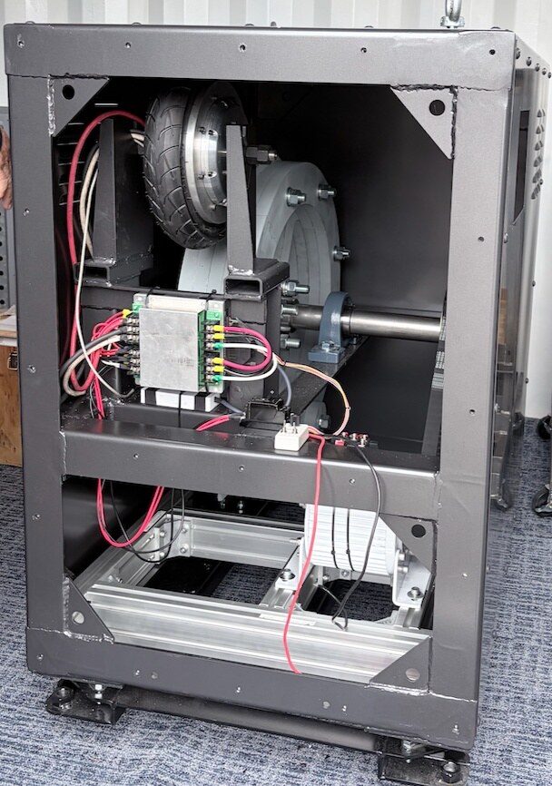
The apparatus consists of a motor, a patented-geometry flywheel, a transmission stage, a permanent-magnet generator, a lithium-ion battery, and a control / SOC-monitoring subsystem. At start-up the battery supplies DC power to the motor, which spins up the coupled flywheel. Inertial rotation of the flywheel drives the generator through the transmission; a portion of the resulting electrical output is stored back in the battery, and the remainder is re-circulated to the motor drive.
3Summary of Patent Claims · Technical Provisions
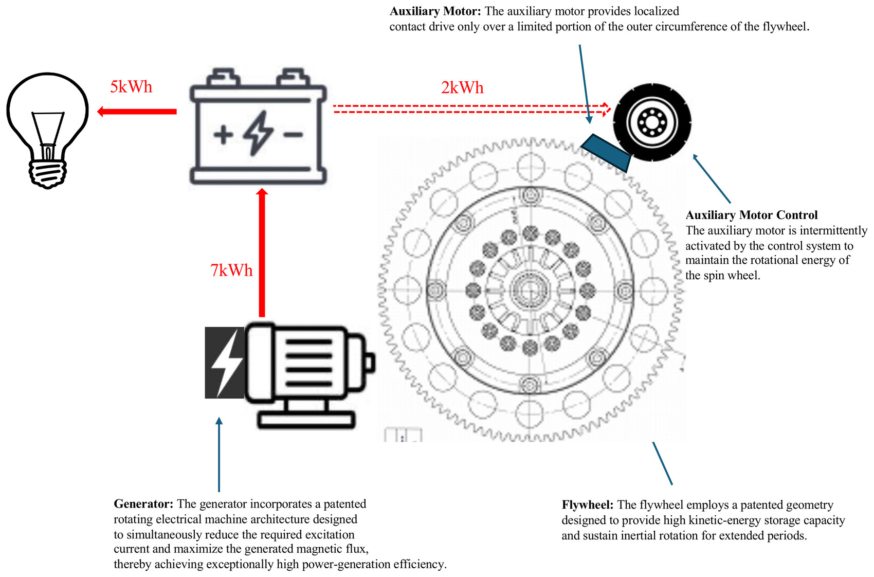
- 01 Flywheel The said flywheel, by virtue of a patented geometric form, secures a high kinetic-energy storage capacity and is configured to sustain inertial rotation over an extended interval.
- 02 Rotating Machine The said rotating machine, through the adopted patented structure, favourably reconciles suppression of excitation current with maximisation of generated magnetic flux, thereby delivering high generation efficiency.
- 03 Generated Power Operation of the said rotating machine yields 7 kWh (5 kW output class) of electrical energy, which is charged into the downstream storage battery.
- 04 SOC Control The said control system executes intermittent start-up control of the auxiliary motor, on the condition that the state of charge (SOC) of the said storage battery lies within the configurable range of 30% – 80%.
- 05 Contact Drive During operation of the said auxiliary motor, intermittent contact drive is applied only to the local protrusions formed on the outer circumference of the said flywheel; this replenishes the rotational energy of the spin-wheel and thereby maintains its rotation.
4Energy Balance Schematic
5Energy Circulation Flow
Start-up
Motor
Flywheel
Generator
+ Re-drive
6Short-Loop Magnetic-Force Motor
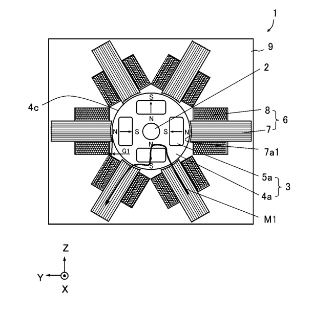
The rotating machine has two rotor cores in which permanent magnets are placed every 90° around the output shaft, with corresponding magnets on opposite rotors set to opposite polarity. Around the rotors, U-shaped stator cores are placed every 60° (or every 30° in an alternative configuration), each carrying a concentrated winding. Both rotor and stator cores are laminated electrical-steel bodies. The claim centres on combining M1 on the first-rotor side, M2 passing between the two rotors, and M3 on the second-rotor side into a single closed-loop magnetic circuit.
7Patented Flywheel Geometry
8SOC Supervision & Auxiliary Motor Control
The control system executes intermittent start-up of the auxiliary motor on the condition that the battery state of charge (SOC) lies within the configurable range 30–80%. The auxiliary motor engages only with the localised protrusions on the flywheel's outer circumference, replenishing the spin-wheel's rotational energy.
9Field Demonstration
In a three-day trial with the prototype, residential loads operated continuously under a generation output of 1 kW · 24 kWh/day. The load breakdown is shown in the table and workload chart below.
| Load | Rated | Operating condition |
|---|---|---|
| Air conditioner6-tatami · cooling | 440 W | Continuous 3 days · 24 h/day |
| LED lightingCeiling × 1 | 40 W | Illuminated 14 h/day |
| FanDC · medium output | 30 W | Continuous 3 days · 24 h/day |
10Patents & International Filings
回転電機
発電装置
11Award & Future Outlook
Japan Resilience
Award — Excellence
Looking ahead, research is underway to combine the ultra-low-loss electromagnetic conversion route with single-walled carbon nanotubes (SWCNT). The high strength and elasticity of SWCNT open the possibility of accumulating kinetic energy from sources previously considered too faint to harness — including human ambulation — and, in the longer term, of powering in-body devices such as artificial hearts. Nevertheless, deployment prioritises disaster-resilience use cases first: corporate BCP, municipal disaster preparedness, regional resilience, and installation in areas with weak grid infrastructure proceed in parallel.
12Conclusion
This system functions as a self-sustaining distributed power source independent of the external grid, combining a patented rotating machine and flywheel geometry with SOC-supervised control of the auxiliary motor. Field-trial results demonstrate three days of continuous operation against residential loads in the 100–240 V range. Further improvement should rest not on abstract commitments but on standardised measurement of SOC, energy balance, and operating hours at each installation site.
超低損失電磁変換技術による自立型分散発電システムの構成と実証 An Ultra-Low-Loss Electromagnetic Conversion Route for High-Density, Self-Sustaining Distributed Power
本稿は、災害時および電力インフラの脆弱な地域における安定した電力供給を目的として株式会社 AEL が開発した「高効率エネルギー循環システム」の構成と実証結果を報告する。中核となる超低損失電磁変換技術は、特許取得済みのショートループ磁力モーター(SLMFM)とコアレス構造を組み合わせ、コギングおよび軸受摩擦に由来するエネルギー損失を抑制する。バッテリーから初動電力を得たモーターが特許形状フライホイールを回転させ、その慣性回転エネルギーを永久磁石発電機で電力へ変換し、生成電力の一部を再度モーター駆動へ循環させる構造をとる。実証実験では 1 kW(24 kWh/日)の発電量により、6 畳用エアコン・LED 照明・扇風機の 3 日間連続稼働が確認された。100 V〜240 V の使用環境に対応可能である。
1序論 · 開発の背景
電気代を気にせず電気を使えないか。災害時にインフラがなくても即座に電力を確保できないか。この二つの問いから、株式会社 AEL の高効率エネルギー循環システムは開発された。屋外イベント・移動販売・レジャー、電力インフラが十分でない地域、そして企業・自治体の事業継続計画(BCP)に至るまで、応用範囲は広い。
2024 年の能登半島地震では 800 を超える携帯電話基地局で電波の送受信が困難となった。停電と通信途絶が同時に発生する事象に対し、外部系統に依存しない自立型分散電源の社会的必要性は増している。
2装置構成
装置は、モーター、特許形状フライホイール、伝動装置、永久磁石発電機、リチウムイオンバッテリー、および制御・SOC 監視系から構成される。初動時にバッテリーから DC モーターへ電力を供給し、モーターに連動するフライホイールを起動する。フライホイールの慣性回転が伝動装置を介して発電機を駆動し、発生した電力の一部をバッテリーへ蓄積、残余をモーター駆動へ再循環させる。
3請求項の要旨 · 本設備の技術的特徴
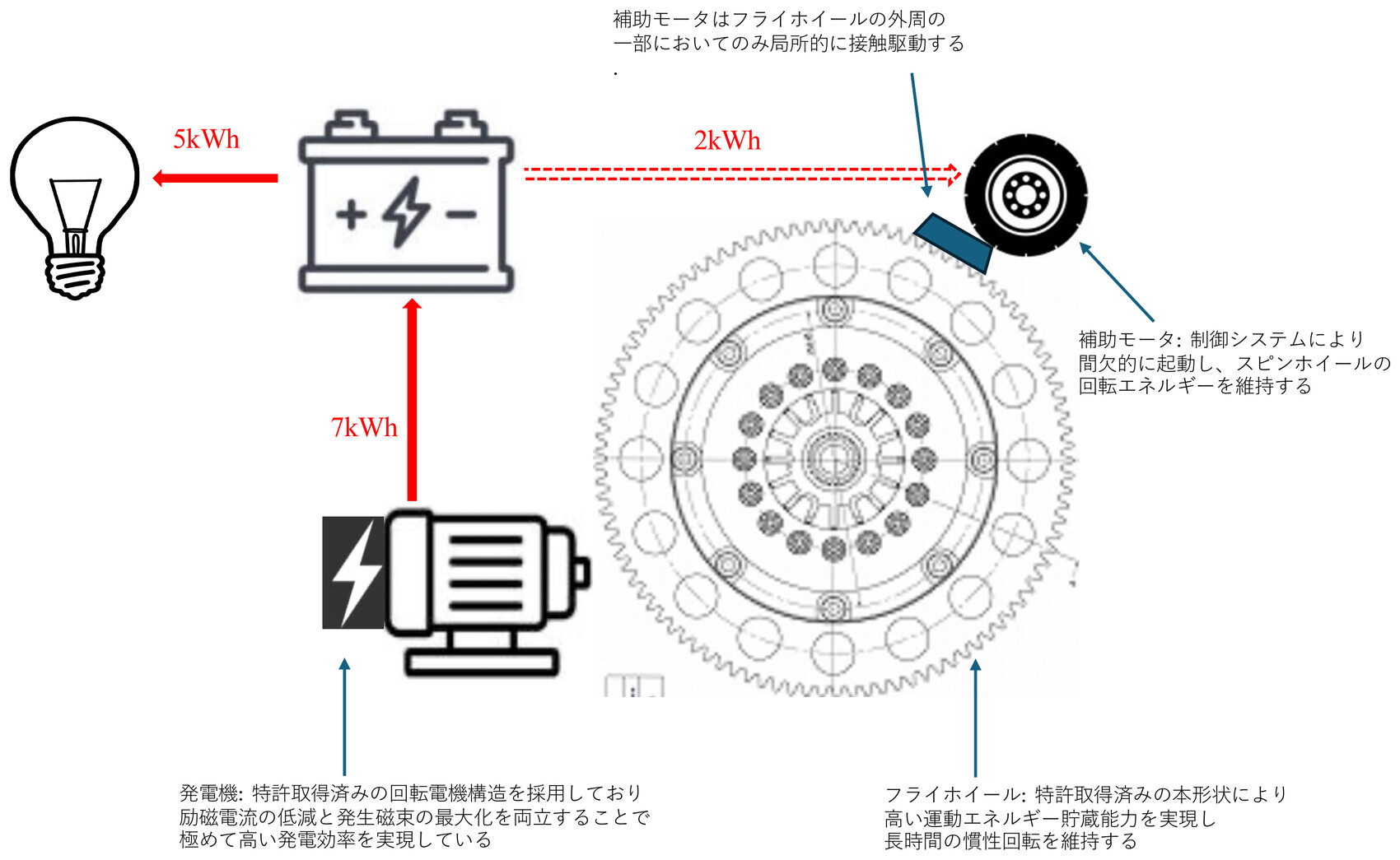
- 01 フライホイール 前記フライホイールは、特許固有の幾何学的形状を備えることにより、高い運動エネルギー貯蔵容量を担保し、長時間の慣性回転を維持可能に構成されている。
- 02 回転電機 前記回転電機は、特許構造の採用により、励磁電流の抑制と発生磁束の最大化とを好適に両立し、高効率な発電性能を発揮する。
- 03 発生電力量 前記回転電機の駆動により、7 kWh(5 kW 出力型)の電力量が生成され、当該電力は後段の蓄電池に充填される。
- 04 SOC 制御 前記制御システムは、前記蓄電池の充電状態(SOC)が 30% 〜 80% の可変設定範囲内にあることを条件として、補助モーターの間欠的な起動制御を実行する。
- 05 接触駆動 前記補助モーターの稼働時、前記フライホイールの外周に形成された局所的な突起部に対してのみ間欠的な接触駆動がなされ、これにより前記スピンホイールの回転エネルギーが補填されてその回転が維持される。
4エネルギー収支模式図
5エネルギー循環フロー
初動供給
モーター
フライホイール
発電機
+ 再駆動
6ショートループ磁力モーター
回転電機は、出力軸を中心に 90° 毎に永久磁石を配置した 2 枚のロータコアを持ち、対応する永久磁石を互いに逆極性とする。その外周には U 字形ステータコアが 60°(別構成では 30°)毎に配置され、各ステータコアには集中巻きの巻線が施される。ロータコア・ステータコアはいずれも電磁鋼板積層体である。第 1 ロータ側の M1、両ロータ間を通る M2、第 2 ロータ側の M3 を結合してループ状磁気回路を構成する点が請求項の中核となる。
7特許形状フライホイール
8SOC 監視と補助モーター制御
制御システムは、バッテリーの充電状態(SOC)が可変設定範囲 30–80% にあることを条件として、補助モーターの間欠起動制御を実行する。補助モーターはフライホイールの外周に形成された局所的突起部にのみ接触駆動され、スピンホイールの回転エネルギーを補填する。
9実証結果
試作機による 3 日間の実証実験では、発電量 1 kW · 24 kWh/日 の条件下で、想定される家庭内負荷が連続稼働可能であることが確認された。負荷内訳は下表および図 4 に示す。
| 負荷機器 | 定格 | 稼働条件 |
|---|---|---|
| エアコン6 畳用 · 冷房 | 440 W | 連続 3 日 · 24 h/日 |
| LED 照明シーリング × 1 | 40 W | 点灯 14 h/日 |
| 扇風機DC · 中出力 | 30 W | 連続 3 日 · 24 h/日 |
10特許・国際展開
Rotating Electrical Machine
Power Generation Apparatus
11受賞および将来展望
ジャパン・レジリエンス
アワード 優秀賞
将来展望として、超低損失電磁変換技術と単層カーボンナノチューブ(SWCNT)を組み合わせる研究開発が進められている。SWCNT の高強度・高弾性という特性により、従来は微弱すぎて利用が困難であった歩行等の運動エネルギーの蓄積が可能となり、将来的には人工心臓等の体内デバイスへの応用も想定される。ただし社会実装は災害対策を最優先とし、企業 BCP、自治体防災、地域レジリエンス強化、電力インフラの脆弱な地域への導入を並行して進める。
12結論
本システムは、特許取得済みの回転電機とフライホイール形状の組合せに、SOC 監視下の補助モーター制御を加えることで、外部系統に依存しない自立型分散電源として機能する。実証実験の結果は、100–240 V の家庭内負荷に対して 3 日間の連続稼働が可能であることを示す。今後の改善は、抽象的な理念ではなく、各導入サイトにおける SOC・エネルギー収支・稼働時間の標準化された測定に基づくべきである。